
So, you read our list of five cool projects for the zombie apocalypse, as described in the book the Maker’s Guide to the Zombie Apocalypse ($25), and thought: “Man, that’s all well and good, Merv, but how about letting me try one of those projects on for size before I buy the book?”
That’s a good question, hypothetical handy but frugal zombie tech project enthusiast. Since you won’t be sold without trying out one of these projects for yourself, we’ve reprinted a fairly straightforward project below. Remember, an ounce of zombie preparation beats an infected bite.
Project 6: PIR Zombie Detector
The second zombie detector project in this book uses a passive infrared (PIR) detector. These detectors are the same type used in intruder alarms—they sense movement of heat—and I guess few things are more intrusive than a group of zombies intent on eating you.
You can of course just buy (or scavenge) an intruder alarm that uses PIR sensors, rather than make this project from scratch, but I thought it would be more fun to make something that uses an Arduino. In fact, if you just add the extra components needed for the PIR alarm to “Project 4: Battery Monitor” on page 53, the same Arduino can both monitor your battery and alert you to a zombie attack, using the same buzzer and display.
When a zombie triggers the PIR sensor, the LCD display will show the message ZOMBIES!! (Figure 4-10). Since the last thing you want to do while fending off a zombie is attract more zombies, this project also allows you to silence the alarm by pressing any button on the LCD shield.
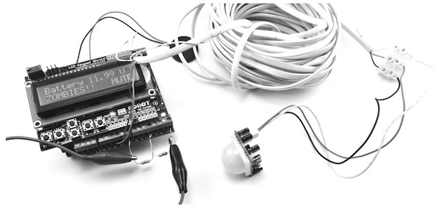
Figure 4-10: PIR zombie detector
What You Will Need
To make this PIR alarm, you’ll need the following parts. If you’ve already made the battery monitor of “Project 4: Battery Monitor” on page 53, you’ll already have the Arduino, screwshield, and alligator clips.

Zombies and PIR Detectors
One important thing that we haven’t discussed is whether zombies can even trigger a PIR detector, which relies on detecting heat.
While zombies are generally considered to be dead, and by implication cold, it isn’t possible to move muscles without also generating a small amount of heat. Also, if the cold zombie walks between a source of heat and the PIR sensor, the sensor will register the movement. So, while zombies are generally cooler than humans, you can expect attacking zombies to register on a PIR sensor.
Construction
This is another project that can be assembled without any soldering, and my instructions assume that you’re building on top of Project 4. If you haven’t already built Project 4, then you’ll need to build a slightly modified version of that project first, as the hardware for the PIR zombie detector is mostly the same.
Step 1: Build the ScrewShield
Flip to Project 4, “Construction” on page 55 and follow Steps 1 to 3. In Step 1, download the sketch (Arduino’s word for program) Project_06_PIR_Alarm from http://www.nostarch.com/zombies/ and use that in place of the sketch for Project 4. Also, when it comes to Step 3, you don’t need to include the two resistors unless you also want to monitor the battery voltage.
Step 2: Make a Lead for the PIR Sensor
There’s little point in making a zombie detector that detects zombies only after they’re already in the same room as you. Chances are you’ll have already thoroughly detected them if they get that far. Therefore, you need to attach a long lead to the PIR detector so that it can monitor the corridor, porch, or other area outside your living space.
The PIR detector has three leads: two that supply power and one output that indicates that motion has been detected. This means you’ll need a three-wire lead. You could find some wire from an intruder alarm, or you could use three of the wires in a telephone extension lead. Pretty much any lead with three or more wires in it will be just fine.
You could either solder the ends of this lead to the lead that comes with the PIR sensor or use a terminal block, as I have (Figure 4-11).

Figure 4-11: PIR lead and terminal block
I harvested my three-lead cable from a telephone extension lead. The cable contained four solid-core insulated wires. These wires were color coded, so I used blue for GND (ground),
orange for 5V, and stripy white for the output; I left the final wire unused. The lead was about 30 feet (9 m) long, which worked fine for the sensor. You can probably use longer leads, but try it out first before you lay all the cabling.
Step 3: Connect the PIR to the ScrewShield
Now that you’ve extended your sensor wires to a useful length, attach the wires to the Arduino screwshield (Figure 4-12; note that the two resistors from Project 4 are shown at the bottom left).
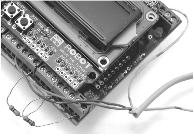
Figure 4-12: Connecting the PIR lead to the Arduino screwshield
If you look at the back of the PIR sensor, you’ll see that the three pins are labeled GND, OUT, and +5V. Connect GND on the PIR sensor to one of the GND connections on the screwshield; it doesn’t matter which one. Then, connect +5V on the PIR sensor to the 5V connection on the screwshield. Finally, connect OUT on the PIR sensor to D2 on the screwshield.
Software
If you just want to make this project on its own, without any of the earlier Arduino-based projects, then use the sketch Project_06_PIR_Alarm. On the other hand, if you’ve made one or more of the other Arduino projects and wish to include them, then use the sketch All_Sensors and change the constants at the top to select the projects that you have made.
The first few lines of the All_Sensors sketch are shown below:
/*
Any projects that you want to exclude from this program should have a
value of “false”. That way, you will not get any false alarms because
of missing hardware.
*/
const boolean project4 = true; // Battery Monitor
const boolean project6 = true; // PIR Alarm
const boolean project10 = false; // Door Monitor
const boolean project11 = false; // Fire Alarm
const boolean project12 = false; // Temperature Monitor
In this case, only the battery monitor (Project 4) and PIR alarm (Project 6) are enabled. If you’ve made more of the projects, then change the value next to those projects from false to true. If you are working your way through this book in order, then the program should look as shown.
All the source code for this book is available from http://www.nostarch.com/zombies/. See Appendix C for instructions on installing the programs.
The PIR detector code follows the same pattern as Project 4, so for more information on how the program as a whole works, please refer to “Software” on page 57. Here, I’ll just describe the code specific to this project.
The first change to the earlier code is the addition of a new constant for the PIR’s OUT pin. I added the pirPIN constant on the line after the switchPin constant.
const int pirPin = 2;
I set pirPin to 2 because the output of the PIR sensor will be connected to pin 2 on the Arduino. The next addition to the sketch occurs in the setup function, where that same pin 2 is set to be an input.
pinMode(pirPin, INPUT);
Although pins on an Arduino default to inputs unless specified as outputs, declaring the pin to be an input makes the code easier to follow.
The loop function now needs to check the sensor, so I added a call to the function checkPIR.
checkPIR();
This new function, checkPIR, will, as the name suggests, check the PIR sensor and take the appropriate action if the sensor is triggered. The function is defined right at the end of the sketch.
void checkPIR()
{
if (digitalRead(pirPin))
{
alarm(“ZOMBIES!!”);
}
}
The checkPIR function makes a digitalRead of the pirPin to decide whether the output from the PIR detector is HIGH or LOW. If movement has been detected, then the alarm function is used to display an appropriate message. For more information on using the inputs and outputs of an Arduino, see Appendix C.
Using the PIR Zombie Detector
The project works well in combination with the battery monitor, as you can just run both off the same battery. But whether you combine the two projects or not, be mindful of your wires when you deploy the PIR detector around your base of operations. If you’re using cable that contains solid-core wires, then affix the cable to the wall at regular intervals along the cable length. Solid- core wires don’t take kindly to being repeatedly flexed.
Scavenged PIR Sensors
The Adafruit PIR module used in this project is designed to work with microcontroller modules like the Arduino. But following an apocalypse, you may find it easier to obtain the type of regular PIR sensor intended for use with a security system, such as the unbranded unit obtained from eBay for a couple of dollars, shown opened up in Figure 4-13.
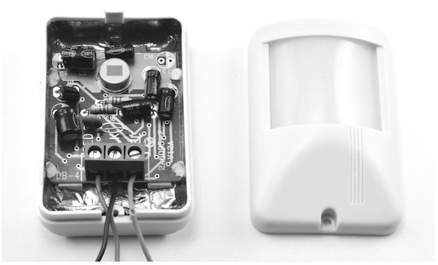
Figure 4-13: A PIR module intended for intruder alarms
This sensor won’t operate at 5V but rather requires a power supply of 12V. The sensor has a logic level output that will rise to 3.6V, which is enough to register as HIGH, just like the Adafruit module. The only difference in wiring is to connect this sensor’s red wire to the Arduino’s Vin rather than to 5V.
Be aware that other sensors may look like this one but have a different output voltage. Some (with an open collector output) require a pull-up resistor (of, say, 1 kΩ) between the output and 5V on the Arduino. If the output of the sensor does not give a useful voltage when you wave your hand in front of it, then it almost certainly needs a pull-up resistor.
Other types of PIR sensors, especially those intended to control lighting, have a relay output. This output works just like a switch, closing when movement is detected. The schematics show how to connect three types of PIR modules to the Arduino (Figure 4-14).
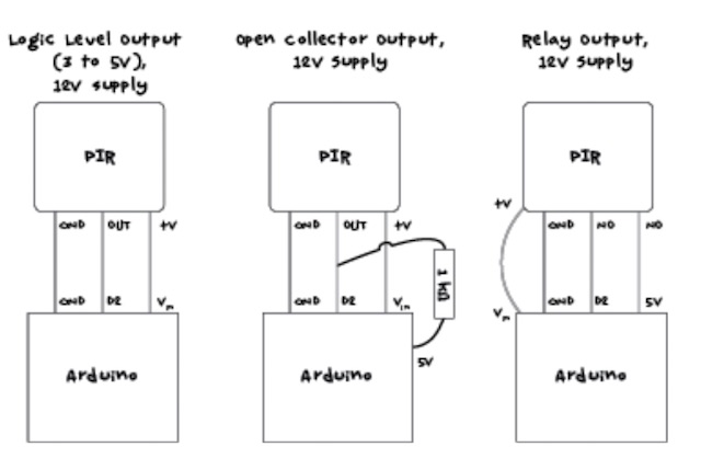
Figure 4-14: Connecting different types of PIR module to the Arduino
Wherever possible, choose a device that you have documentation for so you don’t have to guess how its output works and how to wire it up.
The next chapter advances from automatic zombie detection to walk through a number of surveillance projects that will allow you to see what is going on before it trips over your doorstep. You’ll be able to spot the zombies remotely using webcams.
The preceding was excerpted from the Maker’s Guide to the Zombie Apocalypse ($25) by Simon Monk, courtesy of No Starch Press.
